Earthing system types: TN-S, TN-C-S and TT
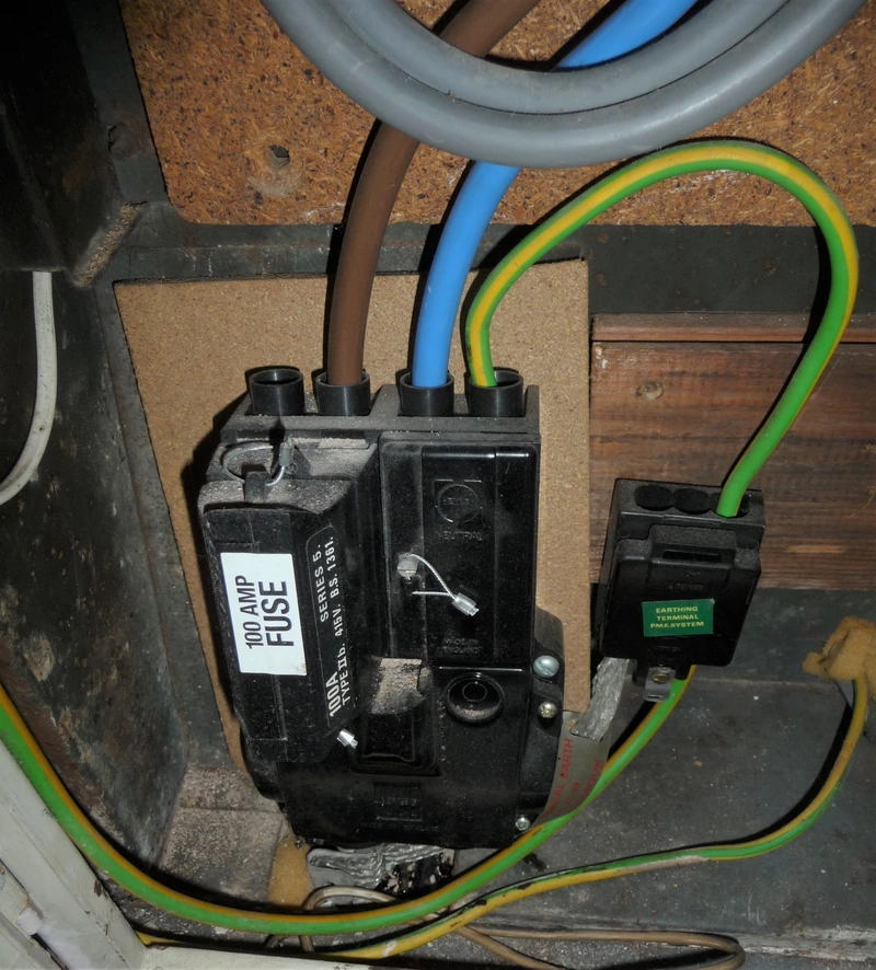 Photo : Rocknrollmancer via Wikimedia Commons
In brief
- British homes use a TN-S, TN-C-S or TT earthing arrangement, and only the distribution network operator can confirm which one a supply actually is.
- A TN-C-S supply, called PME, uses the neutral as the protective path; a broken neutral on those networks can put line voltage on the metalwork of every earthed appliance in the house.
- A TT supply relies on a consumer earth electrode. In a normal domestic design, an RCD provides fault protection because the earth-fault loop is too resistive for a fuse or MCB to disconnect in time.
- For TN supplies, 0.8 ohm for TN-S and 0.35 ohm for TN-C-S are conventional design figures, not identification tests or universal guarantees. For TT, keep the electrode resistance as low as practicable; above 200 ohm it may be unstable.
- A homeowner can look at the service label, the main earthing terminal and visible bonding connections, without removing covers. Whether a metal service needs bonding, and the conductor size, require an assessment.
Earthing is the part of an electrical installation nobody looks at until something goes wrong. It is also the part that decides what happens to the metal case of a faulty washing machine, and whether the protective device in the consumer unit trips fast enough to save the person touching it.
In Britain there are three arrangements in normal domestic use: TN-S, TN-C-S and TT. They are not interchangeable, they are not all equally tolerant of a fault, and the paperwork for a house is only correct if it names the one that is actually there.
I do not identify TN-S from a separate earth conductor at the meter alone. The same visible detail can occur on a TN-C-S network. I check the network information and the installation together, rather than turn a plausible appearance into a declaration on a certificate.
What an earthing system actually does
Public low-voltage distribution commonly uses a three-phase, four-wire network with the neutral earthed at the source. A house may receive a single-phase service from that network; the number of phases does not identify its earthing arrangement.
The Electricity Safety, Quality and Continuity Regulations 2002, regulation 8, cover the earthing of the network. Regulation 8(4) prohibits a consumer from combining neutral and protective functions in one conductor inside the consumer’s installation.
That single sentence explains most of what follows. The supplier may combine neutral and earth on the network side, because the network is engineered for it and monitored. The consumer may not, because the wiring inside a house is not designed, inspected or supervised to the same standard.
An earthing arrangement has one job: give fault current a low impedance path back to the source, so that enough current flows to operate the protective device quickly. The first letter of the code describes how the source is earthed, the second how the exposed metalwork of the installation is earthed.
T means a direct connection to earth; N means a connection to the neutral of the supply; I means isolated from earth. The suffix S means the protective and neutral functions are separate all the way back; C means they are combined in one conductor for part of the run.
| Arrangement | Protective path | Who provides the earth | RCD needed for faults? |
|---|---|---|---|
| Arrangement TN-S | Protective path Separate protective conductor from the substation | Who provides the earth Distribution network operator | RCD needed for faults? No, if Zs is low enough |
| Arrangement TN-C-S | Protective path Combined neutral and earth (PEN), split at the cut-out | Who provides the earth Distribution network operator | RCD needed for faults? No, if Zs is low enough |
| Arrangement TT | Protective path Consumer earth electrode through the soil | Who provides the earth The consumer | RCD needed for faults? Normally yes; overcurrent protection needs a sufficiently low, reliable loop impedance |
TN-S: a separate earth all the way back
In a TN-S supply, the network provides a separate protective conductor from the substation to the property. On older British networks that conductor is often the lead sheath of the service cable, or a copper conductor run alongside it, and the joint is made in the service head or in a separate earthing block next to the meter.
In a genuine TN-S system, neutral and protective functions remain separate along the supply. A lost neutral does not create the same broken-PEN mechanism as TN-C-S. That distinction does not make TN-S immune to every fault: the protective path and the actual network arrangement still need verification.
The disadvantage is age. A lead-sheathed service cable from the 1930s is still a TN-S supply, and the sheath is only as reliable as the joints along it.
Where the sheath has been disturbed, where a service has been replaced in plastic, or where the earth connection at the head has corroded, the reading changes and the certificate has to reflect it.
The relevant supply measurement is Ze, the external earth-fault loop impedance. It assesses the fault path; it does not identify TN-S by itself. The commonly used 0.8 ohm figure is a conventional design value for supplies up to 100 A, not a universal network guarantee.
For circuit design, Zs = Ze + (R1 + R2) links the external impedance to the resistance of the circuit’s line and protective conductors. The result is assessed against the protective device and the required disconnection time, including the appropriate temperature allowance.
On a ring final circuit, continuity and ring-specific tests establish the conductor paths. A plausible loop reading at one socket is not proof that both legs are intact.
TN-C-S: the PME supply most British homes have
PME, protective multiple earthing, is a common form of TN-C-S. A combined protective and neutral conductor, the PEN, serves part of the network; separate neutral and protective conductors then serve the installation.
The split is commonly associated with the service position. Protective neutral bonding (PNB) is another arrangement classified as TN-C-S, so the two terms TN-C-S and PME are not strictly interchangeable.
Regulation 9 of the ESQCR is what makes this legal. It allows the distributor to use the neutral as a combined protective and neutral conductor, on condition that the neutral is earthed at multiple points along the network.
That is the whole safety argument for PME: the more rods in the ground along the run, the lower the resistance of the PEN to earth, and the less the touch voltage rises if the neutral is damaged. The IET quotes the network design figure of 20 ohm for the resistance of the PEN to earth, taken from Engineering Recommendation G12/4.
The economy of PME is obvious. One conductor instead of two, for every service on the street.
The risk is equally obvious once it is stated: the protective conductor of the house shares a conductor with the neutral, so anything that breaks that conductor between the substation and the house removes the earth path and can leave the metalwork live.
What a broken PEN does
An open PEN is the fault that makes TN-C-S dangerous in a way TN-S is not. If the combined conductor breaks, the neutral current of every installation downstream has to find another way back to the substation.
It finds it through the main earthing terminal, the bonding conductors, the incoming water and gas pipes, and the earthed metalwork of every appliance in the house.
An open PEN can raise bonded metalwork above the potential of the surrounding ground. The voltage depends on the connected loads and any alternative return paths; it can become dangerous without an overcurrent device operating.
A conventional RCD does not provide open-PEN protection: line and neutral currents through it can remain balanced while the protective conductors rise in potential. The absence of a trip is therefore not evidence that the supply is safe.
The IET’s worked example in the Broken PEN article makes the arithmetic plain. For a 7 kW load and a 50 V touch voltage limit, the resistance of the alternative path would need to be about 2.1 ohm to keep the metalwork safe.
A typical set of bonding and pipework will not be anywhere near that, which is why a broken PEN is treated as a serious incident rather than a nuisance.
Attention
Lights that brighten when a heavy appliance starts, a hum from the consumer unit, or a tingle from a tap can all be signs of a neutral problem on a PME supply. Treat any of them as a reason to stop using the installation and call the distribution network operator, not just an electrician. The DNO owns the cut-out and the service, and a broken PEN is their fault to fix.
The parts of a PME supply you can see
The service head carries the label. On a PME supply it usually says so, and the earthing terminal is a distinct brass block with a terminal for the earthing conductor of the installation.
Some heads show the letters PME cast into the block itself, which is why the photograph at the top of this article is worth looking at before going to look at your own.
The main earthing terminal, or MET, connects the installation’s earthing and protective bonding system. Circuit protective conductors may reach it through connected earth bars and distribution boards; they do not all need to terminate directly in one physical block.
The terminal and its connections should be identifiable and accessible for inspection by a competent person. A homeowner should not remove an enclosure or loosen a protective connection to follow the route.
Main protective bonding connects extraneous-conductive-parts to the MET. Metal water or gas services can introduce an outside potential, but the mere presence of a metal pipe inside a building does not prove that it needs bonding.
A plastic incoming service without another connection to Earth is not automatically an extraneous-conductive-part. The electrician assesses the actual path, rather than bonding every visible piece of metal.
Under PME conditions, Table 54.8 relates the bonding size to the supply neutral: 10 mm² copper is the usual minimum for a supply neutral up to 35 mm². Network requirements and the actual installation still have to be checked.
For other arrangements, the normal copper bonding rule is at least half the required earthing-conductor size, with a 6 mm² minimum and the applicable upper limit. This is not a universal instruction to fit 10 mm² to every pipe.
TT: when the earth is your own responsibility
A TT supply has no earth provided by the network. The neutral is earthed at the substation as always, but the protective conductor of the installation goes to an earth electrode driven into the ground on the property. Two separate connections to earth, no combined conductor, no shared path with the neutral.
TT is common in rural areas, where the supply arrives on an overhead line and the network cannot guarantee a metallic path back to the substation. It is also the arrangement used where PME is not permitted.
Regulation 9(4) of the ESQCR forbids the distributor from connecting the combined neutral and protective conductor to any metalwork in a caravan or a boat, and the network’s engineering recommendation ER G12/4, which the IET cites, adds fuel filling stations to that list.
In both cases a broken PEN would put a dangerous potential on metal that a person is standing next to or touching while their feet are on the ground.
The earth-fault path of a TT installation includes the ground and both earthing systems. If the total fault-loop impedance is 50 to 200 ohm, a simplified 230 V calculation gives about 1.2 to 4.6 A.
Those currents are below the rating of a 30 A fuse or a B32 MCB. Such a device cannot be relied on to clear that earth fault: waiting longer does not turn a current below its rated value into an overload.
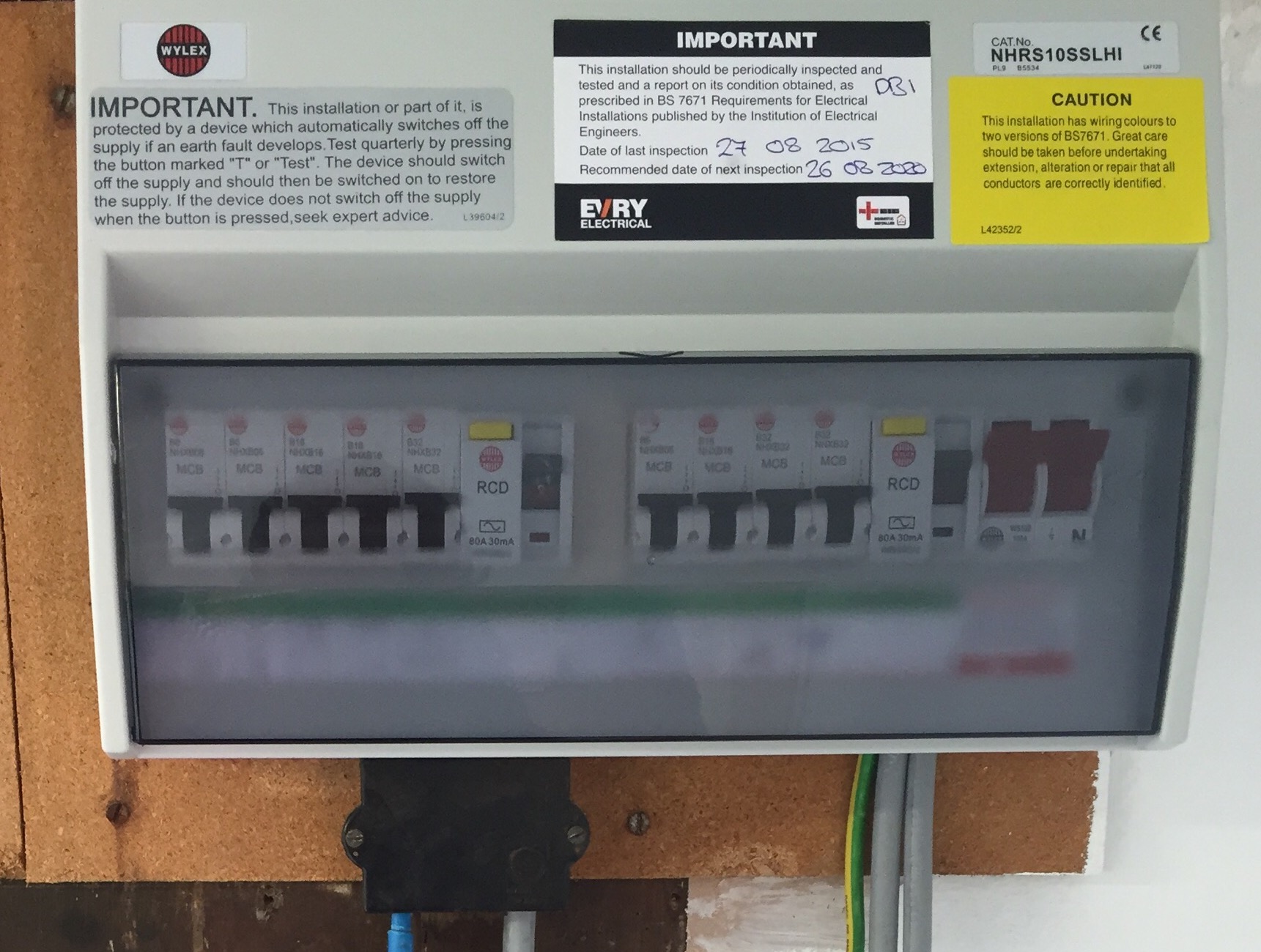
That is why domestic TT installations normally use RCDs for fault protection. BS 7671 also permits overcurrent protection where a sufficiently low and reliable earth-fault loop impedance can be assured, but an ordinary domestic electrode rarely provides that condition.
An RCD and an RCBO can both provide residual-current protection. The design must satisfy the required disconnection time and RA × IΔn ≤ 50 V. For 30 mA, that inequality gives about 1667 ohm, not a recommended electrode resistance.
The IET advises keeping electrode resistance as low as practicable. Values above 200 ohm may not be stable, particularly as moisture and temperature change; 200 ohm is not a target to aim for.
What an earth electrode looks like
An earth electrode is usually a copper-bonded steel rod, driven vertically into the ground, with a clamp and an earthing conductor protected against mechanical damage where it leaves the ground.
BS 7430 is the code of practice that covers the design, and it recognises other forms: tape, plate, structural metalwork that is reliably in contact with earth, and welded reinforcement in a foundation.
Two rules from the IET’s earthing guidance are worth repeating because they are routinely ignored. Rods should be driven into virgin ground, not into backfill or a trench that has already been dug and refilled, because disturbed soil has a higher resistivity.
And where more than one rod is used, the spacing between them should be at least the combined driven depth, otherwise the electrodes sit in each other’s resistance zone and the second rod adds far less than expected.
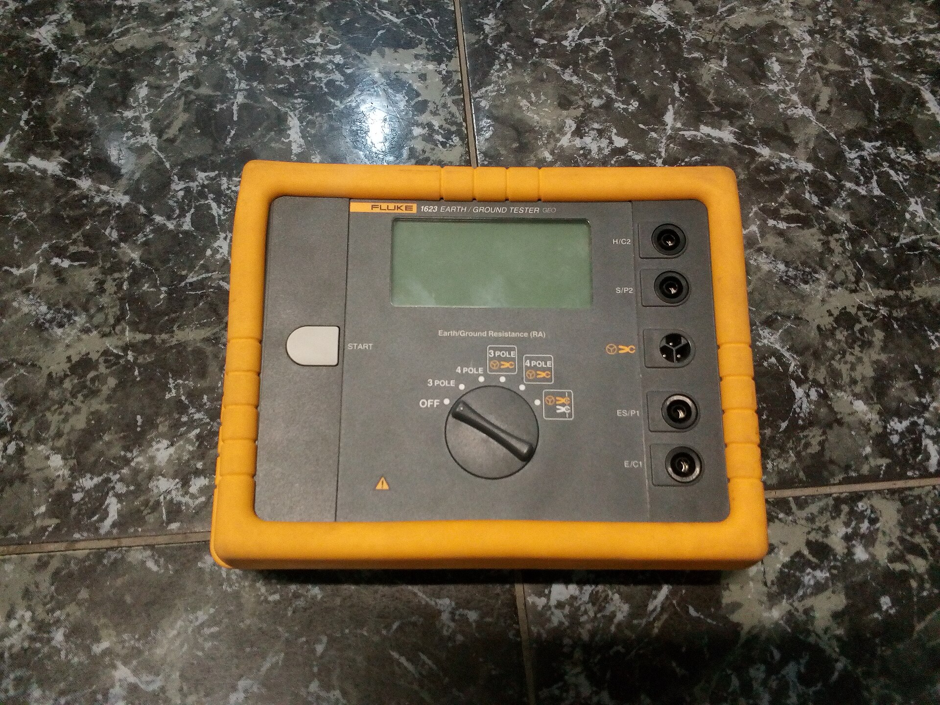
Leave electrical testing to a competent electrician
Do not remove the service cover, disconnect an earthing or bonding conductor, or attempt a live loop test. A competent electrician selects the test method and controls the risks. Homeowner checks are limited to visible labels and accessible exterior connections.
Identifying the arrangement in a real house
The honest answer is that the person who knows is the distribution network operator, and the answer is free.
Every DNO will confirm the earthing arrangement for an address, and the confirmation matters because a TN-C-S installation has different bonding requirements from a TN-S one, and a TT installation needs an electrode that the other two do not.
A separate protective conductor at the origin does not prove TN-S. The network may include a combined PEN conductor further upstream. I obtain the supply arrangement from the distribution network operator and verify the protective measures. A loop-impedance reading assesses performance; it cannot by itself identify the network topology.
The same applies to a property where the service has been replaced: a new plastic service with a separate earth conductor may be TN-S, or it may be a PME supply where the combined conductor has been split further upstream.
A loop reading alone cannot distinguish TN-S from TN-C-S: their measured ranges overlap. On TT, a loop measurement also includes paths beyond the consumer electrode and is not automatically a direct measurement of Ra.
The electrician chooses the verification method and records its basis. Supply characteristics can be obtained by enquiry, while the installation’s effective earthing still has to be verified. Live testing at the origin is not a homeowner check.
| What you measure | TN-S | TN-C-S | TT |
|---|---|---|---|
| What you measure External loop impedance (Ze) | TN-S 0.8 ohm conventional design value; confirm the supply | TN-C-S 0.35 ohm conventional design value; confirm the supply | TT DNO contribution excludes the consumer electrode |
| What you measure Consumer electrode resistance (Ra) | TN-S Assess any additional electrode separately | TN-C-S Assess any additional electrode separately | TT As low as practicable; verify RCD coordination and disconnection |
| What you measure Main bonding conductor | TN-S Half the earthing conductor, 6 mm² minimum | TN-C-S 10 mm² for a neutral up to 35 mm² | TT Half the earthing conductor, 6 mm² minimum |
| What you measure Role of the RCD | TN-S May provide fault protection; additional protection is separately required | TN-C-S May provide fault protection; additional protection is separately required | TT Normally provides fault protection in domestic installations |
What the electrician actually tests
An EICR is where the earthing arrangement stops being a theoretical category and becomes a set of numbers on a schedule. The inspector records the type of earthing as declared by the network, then measures the values that prove the declaration is consistent with the installation.
The supply characteristics and the circuit protective measures are assessed together. Zs may be measured or determined by an appropriate alternative method, such as calculation using measured conductor continuity and the established Ze.
For TT, the electrode and the RCD protection are assessed together. The IET’s guidance on the amended RCD test requires an AC test at IΔn for the standard operating-time check; a 5 × IΔn test is no longer a universal BS 7671 requirement. Manufacturer instructions remain relevant.
Bonding continuity, where bonding is required, is also checked. A recorded supply value does not replace inspection of the connections or verification that the installation is effectively earthed.
Protective-conductor sizing is checked against Chapter 54 and the circuit design. The often-quoted 4 mm² copper minimum concerns a separate protective conductor without mechanical protection, not every CPC contained within a cable.
The earthing conductor is selected by the applicable tabulated or calculation method, with the supply arrangement and network requirements taken into account. Appearance alone does not establish either continuity or adequate cross-sectional area.
Conseil
A satisfactory EICR always comes with a schedule of test results. The earthing type, the Ze, the Zs of each circuit and the RCD trip times are on it. Ask how the supply characteristics were established and how effective earthing was verified. An identified DNO value obtained by enquiry is not the same as an unsupported assumption.
Why this matters to a homeowner
The earthing arrangement changes the fault-protection strategy. A sufficiently low TN fault-loop impedance may allow an MCB to disconnect an earth fault; 30 mA additional protection can still be required independently of that calculation.
On a normal domestic TT design, residual-current protection is central to fault disconnection. A failed RCD must be investigated and the affected circuits must not be treated as protected merely because their MCBs remain switched on.
That is not a subtle distinction for anyone living in a rural property with an overhead line. It is the difference between a fault that trips a breaker and a fault that leaves the metalwork live until somebody touches it.
There is also a straightforward legal dimension. In England’s private and social rented sectors, the Electrical Safety Standards guidance requires the installation to be inspected and tested by a qualified person at least every five years, and a lack of earthing or bonding is one of the defects that makes a report unsatisfactory.
For an owner-occupied house the recommended interval is ten years, and Electrical Safety First’s guidance on periodic inspection and testing is the plain-English version of what the visit covers: adequacy of earthing and bonding, the condition of the switchgear, the wiring system, and the presence of adequate identification.
For a buyer, the practical advice is the same in both cases. Ask for the EICR, check that it names the earthing arrangement, and check that the relevant supply, electrode and bonding entries are completed or their inapplicability explained. Not every field applies to every earthing arrangement.
Faults that keep coming back
A handful of earthing defects recur often enough to be worth naming, because each one has a recognisable signature.
Bonding to the wrong place. Where a service requires bonding, its connection must be on the appropriate metallic section, at the prescribed position near entry, and labelled. A remote connection can leave intervening joints outside the intended protection. Bonding a plastic section makes no electrical connection.
Bonding used as an earth. Somebody runs a 6 mm² conductor from a socket to a radiator pipe and calls it an earth. That is not an earth electrode and it is not a protective conductor; it is a parallel path that can make the pipework live.
The earth pin of a 13 A socket is only a protective connection because the circuit protective conductor behind it goes back to the MET.
A TT installation with no RCD, or with the RCD bypassed. This is the most serious of the group. It happens when an old installation is extended by somebody who does not realise the supply is TT, and it survives until an EICR picks it up.
The opposite mistake is just as common: a device that keeps tripping gets replaced with a less sensitive one instead of being investigated.
An electrode that has never been re-measured. Ground conditions change, and resistance can rise during a dry period. A satisfactory reading at one visit is not a guarantee for every season. The IET’s advice to keep resistance as low as practicable is more useful than designing close to a theoretical ceiling.
Confusing an outbuilding with a caravan. The ESQCR restrictions on caravans and boats do not impose a blanket ban on exporting PME to an ordinary detached garage.
An outbuilding may remain part of the house’s earthing system with correctly designed protective conductors and bonding. A separate TT arrangement is another design option, requiring proper separation and RCD protection; it is not an automatic cure for every garden supply.
How to read your own installation
Start at the service head and look for the PME earthing terminal, the label, and a green-and-yellow conductor leaving it. If there is a separate earth block with a conductor that disappears into the wall or the floor, the property is more likely TN-S or TT, and the difference matters.
Follow the earthing conductor to the main earthing terminal. The installation’s protective-conductor system must remain electrically continuous to it, and the main protective bonding conductors should leave it towards the gas and water entry points.
The clamps should be on the pipe, not on the paint, and there should be a safety label reading “Safety electrical connection, do not remove”.
Look for an earth electrode: a rod, a tape or a plate, usually near the meter position or in a pit outside, with a clamp and a conductor in conduit where it leaves the ground.
If you find one on a property that the paperwork calls TN-C-S, ask why: it may be an additional electrode installed to reduce touch voltage on a long PME run, which is a legitimate design, or it may be a mistake.
Then read the EICR. The type of earthing is on the first page of the schedule, and the Ze or Ra value is on the test results. If those two entries are missing or inconsistent with what you can see at the cut-out, that is the point to ask a question.
| What you see | What it usually means |
|---|---|
| What you see Brass terminal stamped PME on the cut-out | What it usually means TN-C-S: combined neutral and earth to the substation |
| What you see Separate earth block beside the meter, conductor into the wall | What it usually means TN-S, or a TT electrode, or a split PME: confirm with the DNO |
| What you see Rod or tape in a pit outside, conductor into the meter box | What it usually means An electrode is present; it may serve TT or supplement a TN arrangement |
| What you see Bonding clamp on a plastic pipe | What it usually means No bonding at all on that service, even if the conductor is present |
| What you see Green-and-yellow conductor cut and taped | What it usually means A protective conductor that has been disconnected: an immediate defect |
The question I ask before quoting any work
Before planning an additional circuit, an EV charger or a consumer-unit replacement, I establish the supply arrangement and protective measures. A low Ze and adequate bonding are important, but they do not complete the design: outdoor EV charging on PME also requires the applicable open-PEN protection assessment.
The same house with a Ze of 1.4 ohm, no bonding on the gas, and a certificate that says TN-S is a different quotation, because the earthing has to be resolved before anything is added to it.
The point of earthing is not to have an earth connection on the certificate. It is to make sure that, when a fault happens, the voltage that appears on metalwork stays low enough for long enough, and that the device protecting the circuit operates before a person becomes part of the path.
TN-S, TN-C-S and TT are three different answers to that problem, with three different sets of numbers and three different failure modes. Knowing which one you have is the first step, and it is the step most often skipped.
How do I know if my house is TN-S, TN-C-S or TT?
The service head and an electrode provide clues, not a complete identification. A separate earth conductor does not prove TN-S, and a rod can supplement TN-C-S. Confirm the arrangement with the distribution network operator and have the installation’s protective measures verified.
Is a TN-C-S supply dangerous?
Not in normal operation, but it carries a risk that TN-S and TT do not. The protective conductor shares a path with the neutral, so a broken PEN can raise the metalwork of the whole installation to a dangerous touch voltage without tripping anything. That is why the network earths the PEN at multiple points, and why regulation 9(4) of the ESQCR forbids a PME connection to the metalwork of a caravan or a boat.
Why does a TT system need an RCD?
In an ordinary domestic TT installation, the earth-fault loop is too resistive for an MCB to disconnect in time, so an RCD normally provides fault protection. The design must satisfy RA × IΔn ≤ 50 V and the required disconnection time. Overcurrent protection is only an alternative where a sufficiently low, reliable loop impedance is assured.
What is a good earth electrode resistance?
Aim for as low as practicable, not a particular value close to the limit. The IET warns that values above 200 ohm may be unstable. The approximately 1667 ohm result for a 30 mA RCD is a calculation ceiling under the relevant conditions, not a legal target or a recommendation.
Can I check my own earthing?
You can inspect visible labels and connections without removing covers or disconnecting conductors. Live loop tests, electrode tests and decisions about bonding belong to a competent electrician. Different tests use different methods; none is made safe merely by owning a multimeter.
Does an EICR tell me the earthing arrangement?
An EICR records the earthing arrangement and the relevant verification results. Supply characteristics may be established by a permitted method such as DNO enquiry or measurement. Ask the inspector to explain the recorded basis and how effective earthing was verified; a low reading alone does not identify TN-S.

Théo Desrousseaux
Electrician and editor
I work in the field and edit this magazine. Every guide is reviewed for its target country before publication.
Author → Credentials → Editorial method → Report a factual correction →
No email app? Copy the correction details
Email address and prefilled context:
theo@sparx-elec.fr
Article: https://www.sparx-elec.com/gb/earthing-system-types/
Edition: GB — English
Factual issue: [describe the factual issue]
Passage: [quote or identify the passage]
Source: [optional source URL]
Sources and references
- 1. IET — Earthing, Wiring Matters Autumn 2011 Official
- 2. IET — TT earthing considerations, Wiring Matters September 2021 Official
- 3. IET — Broken PEN, Wiring Matters March 2021 Official
- 4. legislation.gov.uk — Electricity Safety, Quality and Continuity Regulations 2002, regulation 8 Official
- 5. legislation.gov.uk — Same regulations, regulation 9 (protective multiple earthing) Official
- 6. Electrical Safety First — Earthing and bonding Official
- 7. Electrical Safety First — Periodic inspection and testing Official
- 8. GOV.UK — Electrical safety standards in the private and social rented sectors: guidance Official
- 9. IET — Part P, England and Wales Official
- 10. IET — Minimizing unnecessary live testing for initial verification (2025) Official
- 11. IET — Responsibilities for electrical installation designers: outbuildings Official
- 12. IET — Earth fault loop impedance and ENA P23 Official
- 13. IET — Protective bonding habits Official
More guides
Practical electrical installation guides, diagnostic methods and tool recommendations compared against the technical wiring standards of this national edition.
UK 13 amp socket types BS 1363 explained
What are the UK 13 amp socket types? Learn the BS 1363 plug, the fuse in the plug, safety shutters, the Type G standard, and how the system works.
Read the guide Guide RCD test button not tripping An RCD test button that does not trip means the device failed its own check. What the button proves, the causes, and the checks you can make safely. Read the guide
 Guide Outdoor lighting cable UK: which cable, how deep Which cable to run to UK outdoor lights, how deep to bury it, how to fit a CW gland, and how to size a long garden run for voltage drop. Read the guide
 Guide RCBO vs RCD difference UK consumer unit What is the difference between an RCBO and an RCD? Learn what each device protects, why RCBOs trip less, the cost in the UK, and which to choose. Read the guide