Ring main circuit wiring UK BS 7671
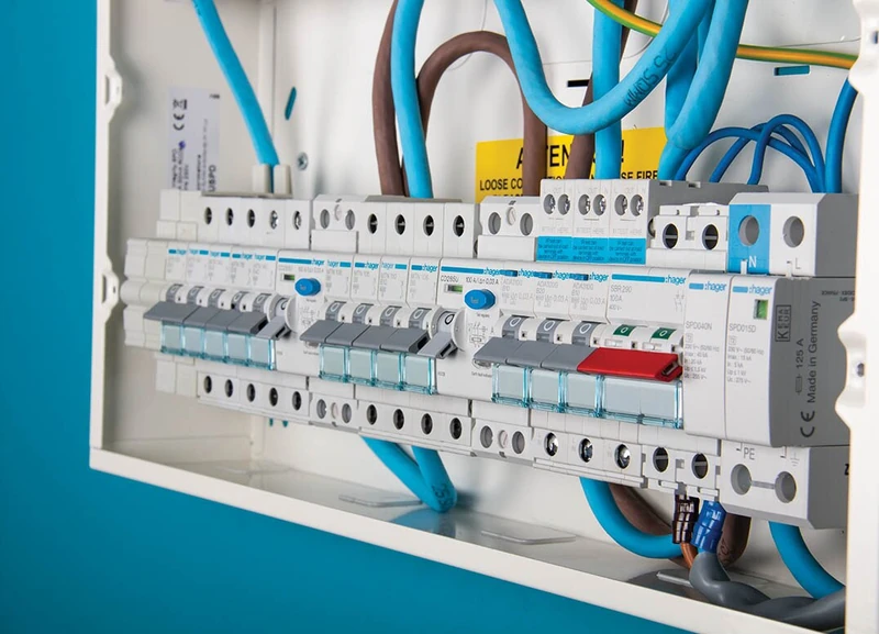 Photo : Hager UK
 In brief
- A ring final circuit starts at the consumer unit, loops around the floor and returns, so current flows both ways and the load is shared between the two halves of the cable.
- Under BS 7671 rule 433.1.204, a ring circuit can feed an unlimited number of 13 A sockets, with a recommendation that the floor area does not exceed 100 m².
- The ring is protected by a 32 A circuit breaker and typically wired in 2.5 mm² cable.
- An unfused spur from a ring can feed one single or double socket, or one fused connection unit, wired in the same cable as the ring.
- If the live or neutral of a ring is broken, the circuit keeps working but loses its protection; a broken earth leaves it without a safety earth.
A ring main circuit, properly called a ring final circuit, is a loop of cable that starts at the consumer unit, runs around the floor or storey, and returns to the same circuit breaker. Because the cable forms a ring, current can flow in both directions, and the load is shared between the two halves of the loop. This is the standard way sockets are wired in most UK homes.
Under British Standard BS 7671 rule 433.1.204, a ring final circuit consists of a continuous 2.5 mm² cable loop starting and ending at a 32 A circuit breaker, serving a floor area up to 100 m² with an unrestricted count of 13 A socket outlets. Wiring spurs requires strict rules: an unfused spur feeds one single or double socket, while fused connection units protect secondary branch circuits.
32 A
circuit breaker protecting a ring final
100 m²
recommended maximum floor area per ring
2.5 mm²
typical cable size for a ring circuit
2
directions current can flow in the loop
How a ring final circuit works
A ring final circuit is a loop. The cable leaves the consumer unit, runs around the perimeter of the floor or storey, and returns to the same point. The live, neutral and earth conductors each form a complete loop, and the sockets are connected into the loop at intervals.
Because the loop returns to the consumer unit, the current to any socket can flow from either direction. In practice, the current splits between the two halves of the loop, so each half carries only part of the load. This is what allows a 32 A breaker to protect a circuit that could theoretically supply more than 32 A of sockets: the load is distributed around the ring.
The loop design also means that a socket at one end of the ring is fed from both directions. If the ring is intact, the current is shared. This is the fundamental difference between a ring circuit and a radial circuit, which is a single cable running from the consumer unit to the last socket.
| Feature | Ring final circuit | Radial circuit |
|---|---|---|
| Feature Cable path | Ring final circuit Loop returning to the consumer unit | Radial circuit Single run from the consumer unit |
| Feature Current flow | Ring final circuit Both directions, load shared | Radial circuit One direction |
| Feature Typical cable | Ring final circuit 2.5 mm² | Radial circuit 2.5 mm² or 4.0 mm² |
| Feature Protection | Ring final circuit 32 A | Radial circuit Depends on cable and design |
| Feature Typical use | Ring final circuit Sockets in UK homes | Radial circuit Sockets, lighting, fixed appliances |
Ring and radial circuits compared (Elec-Mate, Total Skills).
The BS 7671 rule 433.1.204
The ring final circuit in the UK is governed by rule 433.1.204 of BS 7671, the IET Wiring Regulations. This rule allows an unlimited number of 13 A socket outlets to be installed on a ring circuit, with a recommendation in Appendix 15 that the floor area served does not exceed 100 m² and that the load is reasonably distributed around the ring.
The rule exists because the ring design distributes the load between the two halves of the loop. As long as the load is reasonably distributed, the 32 A protection is adequate even though the total socket capacity could be higher. The 100 m² recommendation keeps the loop short enough that the voltage drop and the load distribution remain manageable.
In practice, most small and medium houses have one ring circuit per storey, with larger premises having more. An installation designer may determine if additional rings are needed based on the floor area and the expected load.
How the ring is protected
A ring final circuit is protected by a 32 A circuit breaker. The breaker protects the cable against overload and short circuit. Because the load is shared between the two halves of the loop, the 32 A rating is sufficient for the cable size and the expected load.
The protection is one of the reasons the ring design works. If the ring were a single cable carrying the full load, it would need a larger cable or a lower-rated breaker. The loop design allows the 32 A breaker to protect the circuit while the load is distributed.
The circuit is also protected against earth leakage by the RCD or RCBO in the consumer unit. The combination of the 32 A breaker for overload and the RCD for earth leakage provides the full protection for the ring circuit.
The cable size
A ring final circuit is typically wired in 2.5 mm² cable. The cable size is chosen so that, with the load distributed around the loop, the 32 A protection is adequate and the voltage drop is within limits.
The cable size matters because the ring design relies on the load being shared. If the cable were too small, the loop could overheat even with the load distributed. The 2.5 mm² cable is the standard choice for domestic ring circuits, and it is the size assumed by the design rules.
A radial circuit, by contrast, may use 2.5 mm² or 4.0 mm² depending on the configuration and the load. The larger cable in a radial circuit compensates for the fact that the current flows in one direction only.
Spurs from a ring circuit
A spur is a branch from the ring that feeds a socket or a fused connection unit. An unfused spur from a ring circuit, wired in the same cable as the ring, is allowed to run one socket, single or double, or one fused connection unit. This is the standard rule for spurs.
The limit on spurs exists because a spur is not part of the loop, so it does not benefit from the load sharing. A spur carries its full load in one direction, which is why it is limited to one socket or one fused connection unit. A fused connection unit adds its own fuse, which protects the spur cable.
Before 1970, the rules on spurs were different, and some older installations have more spurs than the current rules allow. An electrician inspecting an older installation will check the spurs against the current rules.
The failure modes of a ring circuit
The ring design has a weakness that the installer must understand. If the live or neutral conductor of the ring is broken, the circuit continues to work, because the sockets are still fed from one end of the loop. But the protection is compromised, because the load is no longer shared and the cable may be overloaded.
If the earth conductor is broken, the circuit works but with no safety earth connection. This is a serious fault, because the sockets are no longer earthed. The fault may not be obvious, because the sockets still work, which is why testing the ring is essential.
An inadvertent cross connection between two 32 A rings means that the fault current protection reaches 64 A and the required fault disconnection times are violated grossly. This is why testing at installation is essential, and why the ring continuity must be verified.
Testing a ring circuit
Testing a ring final circuit is a specific procedure that verifies the loop is intact. The continuity of each conductor is measured, and the readings at the ends of the ring are compared. The test confirms that the live, neutral and earth conductors each form a complete loop.
The test also verifies the polarity and the earth continuity. A ring with a broken conductor will show an incorrect reading, even though the sockets still work. This is why the ring continuity test is an essential part of the installation testing.
The results are recorded on the electrical installation certificate. The test is repeated as part of the periodic inspection, and any fault found is corrected before the circuit is used again.
Ring or radial: which to choose
The choice between a ring and a radial circuit depends on the installation. On socket circuits I let the expected load decide the layout, not habit. The ring is the traditional UK choice for sockets, and it is well suited to distributing a moderate load over a floor area. The radial circuit is simpler, with a single cable run, and it is often used for lighting and for circuits where the load is concentrated.
For a new installation, the designer considers the floor area, the expected load and the cable route. Both arrangements are compliant with BS 7671, and the choice is a design decision. The ring remains the standard for domestic sockets in the UK, while radials are common for other circuits.
The history of the ring circuit
The ring final circuit was developed in the United Kingdom after the Second World War as a way to wire sockets economically. The post-war reconstruction needed a socket system that could be installed quickly and with less copper than the alternatives, and the ring design achieved that by sharing the load between two halves of a loop.
The design was adopted as a British standard and became the default for domestic socket circuits. Over the decades, the rules were refined, and the current rule 433.1.204 of BS 7671 codifies the design limits, including the 100 m² floor area recommendation.
The history explains why the ring is so common in the UK and so rare elsewhere. Most other countries use radial circuits, which are simpler to design and test. The ring is a distinctly British solution, and it remains the standard for domestic sockets in the UK.
How the load is shared around the loop
The key to the ring design is load sharing. When a socket in the middle of the ring draws current, that current flows from both directions: part comes from one half of the loop and part from the other. Each half of the cable carries only a portion of the total load.
This sharing is what allows the 32 A breaker to protect the circuit. If the full load flowed through a single cable, the cable would need to be larger or the breaker smaller. The loop distributes the current, so the 2.5 mm² cable and the 32 A protection are adequate.
The sharing only works if the ring is intact. If one half of the loop is broken, the full load flows through the remaining half, which can overload the cable. This is why the continuity of the ring must be tested.
The role of the RCD in a ring circuit
A ring final circuit is protected against overload and short circuit by the 32 A breaker, and against earth leakage by the RCD or RCBO in the consumer unit. The two protections work together: the breaker protects the cable, and the RCD protects people.
The RCD protection is particularly important for a ring circuit feeding sockets, because sockets are used by people and by portable appliances. A fault in an appliance or a damaged cable can create an earth leak, and the RCD detects it and cuts the power.
In a modern consumer unit, the ring circuit is often protected by an RCBO, which combines the 32 A overcurrent protection and the RCD protection in one device. This gives the ring circuit its own dedicated protection, so a fault on the ring does not trip other circuits.
The floor area limit explained
The 100 m² floor area recommendation in Appendix 15 of BS 7671 is a design guide, not a hard limit. It exists to keep the loop short enough that the voltage drop is within limits and the load is reasonably distributed.
A ring circuit serving a floor area much larger than 100 m² could have a voltage drop that is too high, or a load distribution that is too uneven. The designer can exceed the 100 m² limit if the calculations justify it, but the recommendation is a sensible default.
In practice, most small and medium houses have one ring circuit per storey, which keeps each ring within the recommended area. Larger premises have more rings, each serving a portion of the floor.
Wiring a socket into the ring
A socket is wired into the ring by connecting the live, neutral and earth conductors of the loop to the socket terminals. The loop passes through each socket, so the conductors continue from one socket to the next around the ring.
The connection must be made correctly at each socket, because the ring depends on the continuity of the loop. A poor connection at one socket can break the loop, even if the socket itself works. This is why the quality of the connections matters.
The socket is mounted in a back box, and the faceplate is fixed over it. The earth connection is made to the socket and often to the back box, providing a continuous earth path around the ring.
Common faults in ring circuits
The most common fault in a ring circuit is a broken conductor. On a ring fault I start at the consumer unit and follow the loop one outlet at a time. Because the sockets still work when the loop is broken, the fault is not obvious, and it is only found by testing. A broken live or neutral leaves the circuit working without proper protection.
The second common fault is a poor connection at a socket or at the consumer unit. A loose connection creates resistance that heats up under load, and it can break the loop. The heat can damage the cable and the socket.
The third fault is an incorrect spur. A spur that feeds more than one socket, or a spur wired in a smaller cable, is a breach of the rules and can overload the spur cable. An electrician inspecting an older installation will check the spurs against the current rules.
Why testing the ring matters
Testing a ring final circuit is the only reliable way to confirm the loop is intact. The continuity of each conductor is measured, and the readings at the ends of the ring are compared. A broken conductor shows an incorrect reading.
The test also verifies the polarity and the earth continuity. A ring with a broken earth shows a fault even though the sockets work. The test is essential at installation and as part of the periodic inspection.
The results are recorded on the electrical installation certificate. If a fault is found, it is corrected before the circuit is used again. The testing is what makes the ring design safe in practice.
The difference between a ring and a radial circuit
The ring and the radial are the two ways to wire a circuit of sockets. The ring is a loop that returns to the consumer unit, sharing the load between two halves. The radial is a single cable that runs from the consumer unit to the last socket, carrying the full load in one direction.
The radial is simpler to design and test, because there is no loop to verify. It is often used for lighting circuits and for circuits where the load is concentrated at one point. The ring is the traditional UK choice for sockets, because it distributes the load over a floor area with less copper.
Both arrangements are compliant with BS 7671, and the choice is a design decision based on the floor area, the expected load and the cable route. The ring remains the standard for domestic sockets in the UK.
The role of the fused connection unit
A fused connection unit, or FCU, is a device that provides a fused outlet for a fixed appliance. It is wired into the ring as a spur, and it has its own fuse that protects the spur cable and the appliance.
The FCU is used for fixed appliances such as extractor fans, cooker hoods and underfloor heating. Because the appliance is wired directly rather than plugged in, the FCU provides the fuse that would otherwise be in the plug.
The fuse in the FCU is sized to the appliance, typically 3 A or 13 A. The FCU also provides a means of isolation, so the appliance can be isolated for maintenance without switching off the whole ring.
The importance of correct polarity in a ring
Polarity is the correct connection of the live and neutral conductors. In a correctly wired ring, the live conductor is connected to the live terminal and the neutral to the neutral terminal at every socket.
Incorrect polarity is a fault that can leave an appliance live even when it appears to be switched off. It is one of the faults checked during an electrical inspection, and it must be corrected if found.
The polarised design of the BS 1363 plug ensures the appliance is always connected the correct way, but the socket itself must still be wired correctly. The polarity of each socket in the ring is verified during the testing.
When a ring circuit needs to be extended
Extending a ring circuit is a common job, and it must be done correctly to preserve the protection. A new socket can be added as a spur, feeding one single or double socket, or as part of the loop if the ring is opened and extended.
Adding a socket as a spur is the simplest option, but the spur rules limit it to one socket or one fused connection unit. Adding a socket as part of the loop requires the ring to be opened at a convenient point and the new cable to be connected in line.
The extension must use the correct cable size and the connections must be made correctly, because the ring depends on the continuity of the loop. The work should be tested to confirm the loop is intact after the extension.
The voltage drop in a ring circuit
Voltage drop is the reduction in voltage along the length of a cable. In a ring circuit, the voltage drop is lower than in a radial of the same length, because the load is shared between the two halves of the loop.
The 100 m² floor area recommendation keeps the loop short enough that the voltage drop is within the limits of BS 7671. A ring serving a much larger area could have a voltage drop that is too high, which is why the designer checks the calculation.
The voltage drop is one of the design checks recorded on the electrical installation certificate. It is part of the evidence that the circuit is correctly designed.
The future of the ring circuit
The ring circuit has been the standard for UK sockets for decades, but its future is debated. Some designers prefer radial circuits, which are simpler to test and less prone to the failure modes of a broken loop. Others argue that the ring remains a cost-effective way to wire sockets.
The regulations continue to allow both arrangements, and the choice is a design decision. For the foreseeable future, the ring remains the standard for domestic sockets in the UK, and understanding it is essential for anyone working on UK electrical installations.
The key point for the homeowner is that the ring is a proven design, but it depends on correct installation and testing. A ring that is intact and correctly protected is a safe and effective way to supply sockets.
What is a ring main circuit?
A ring main, or ring final circuit, is a loop of cable that starts at the consumer unit, runs around the floor and returns to the same 32 A breaker. Current flows in both directions, so the load is shared between the two halves of the loop.
How many sockets can a ring circuit have?
Under BS 7671 rule 433.1.204, a ring circuit can feed an unlimited number of 13 A sockets, with a recommendation that the floor area does not exceed 100 m² and that the load is reasonably distributed.
What cable is used for a ring circuit?
A ring final circuit is typically wired in 2.5 mm² cable, protected by a 32 A circuit breaker. The cable size and the load sharing are what make the 32 A protection adequate.
What is a spur on a ring circuit?
A spur is a branch from the ring. An unfused spur can feed one single or double socket, or one fused connection unit, wired in the same cable as the ring. A fused connection unit adds its own fuse to protect the spur cable.
What happens if a ring circuit is broken?
If the live or neutral is broken, the circuit keeps working but loses its protection, because the load is no longer shared. If the earth is broken, the circuit works with no safety earth. Both faults need testing to be found, because the sockets still work.

Théo Desrousseaux
Electrician and editor
I work in the field and edit this magazine. Every guide is reviewed for its target country before publication.
Author → Credentials → Editorial method → Report a factual correction →
No email app? Copy the correction details
Email address and prefilled context:
theo@sparx-elec.fr
Article: https://www.sparx-elec.com/gb/ring-main-circuit-wiring/
Edition: GB — English
Factual issue: [describe the factual issue]
Passage: [quote or identify the passage]
Source: [optional source URL]
More guides
Practical electrical installation guides, diagnostic methods and tool recommendations compared against the technical wiring standards of this national edition.
RCD keeps tripping causes
Why does an RCD keep tripping? Learn the common causes, the 30 mA threshold, the six-month test rule, and how to diagnose the fault safely.
Read the guide Guide UK 13 amp socket types BS 1363 explained What are the UK 13 amp socket types? Learn the BS 1363 plug, the fuse in the plug, safety shutters, the Type G standard, and how the system works. Read the guide
  Guide RCBO vs RCD difference UK consumer unit What is the difference between an RCBO and an RCD? Learn what each device protects, why RCBOs trip less, the cost in the UK, and which to choose. Read the guide
 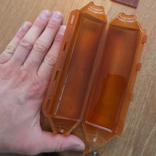 Guide Outdoor waterproof junction box Outdoor waterproof junction boxes: field test of the gel-filled Ready Cast and the Magic Box 65 with cable glands, per local wiring regulations. Read the guide